Mikrotik RB250GS - 5 Port Gigabit Switch

Posted by Admin Saturday, November 5, 2011 0 comments
This little Mikrotik has the same form factor as the 750/750G. It is a 5 porter that I was able to get your standard gigabit speeds through…nothing remarkable there. So why should I buy one?
First, they are shipped to your door for around $40. Not a bad price for a small managed gig switch.
Second it has some interesting features ;) It runs a new OS called Switch OS, SwOS(here’s the wiki on it).

SwOS is only accessible via a web browser. My switch came shipped with OS v1.0. I went ahead and installed 1.1. When upgrading from 1.0 you upload the new OS, then hard reboot the switch. When it comes back up it will be running the new version.
On the system setting there is no entry for subnet mask or default gateway. The switch will simply respond to whatever IP contacts it. What this tells me is that the switch can’t dump any messages out…I really wanted syslog messages out of this guy. It is, however, accessible via SNMP.
Link Screen:

Enable/disable, interface settings etc.

It doesn’t appear as if you can manipulate the MTU on the switch, which probably means no jumbo frame support(*This will be added in version 1.2 with MTU up to 9000*)…which is something I’ve come to expect from a managable gig switch. As a side note, when pinging the switch a max MTU into the CPU of the switch is 1272…not important, but interesting. Statistics Screen:

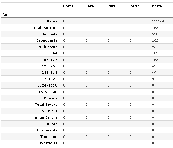
Very decent status section

The status screen covers standard errors, counters on broadcast and unicast, but has some additional entries not commonly seen. It keeps counters on packets of varying sizes as well as fragments. Forwarding Screen:
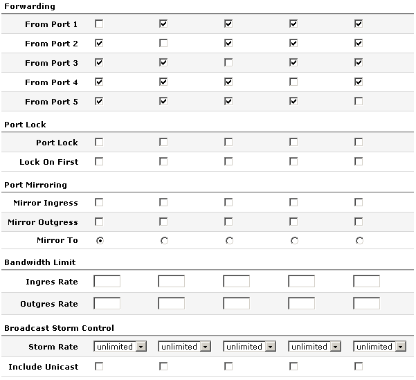
The forwarding section allows you to limit which ports can communicate with other ports. Somewhat like Cisco’s private VLANs.
Port lock prevents MACs from being learned on a port (you would need to do manual entries). Lock on first option allows the switch to only learn the first mac that shows up on the port. This would only be useful for users without IP phones.
Standard mirroring.
Bandwidth limit…I LIKE THIS FEATURE! Hardware rate limiting is missing from a lot of low end manageable switches. The values are expressed in bps.
Storm control, both broadcast and unicast. This is represented as about 20 options ranging from 1k to 1 million.
VLANs Screen:

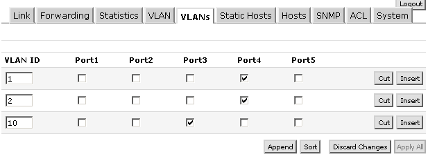
Setting what vlans are on the trunk ports

This screen basically creates the vlan database. The ports you check on this screen send the tagged packets down these ports…you are telling the switch which ports are trunked and what vlans traverse these trunks. These are tagged ports. You don’t need to set a tag on ports that will only be access. VLAN Screen:

vlan powers activate!

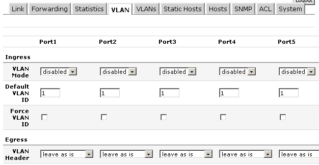
This page is where you configure ports to trunk or be access.
Vlan modes vary. You can accept tagged packets. You can drop untagged packets. You can remark all packets with different vlan tag. You can accept untagged packets into the native vlan. Pretty robust feature set. To have a trunk port first define the vlans in the vlans section, then here on the vlan screen set the port to enable or some derivative.
If you want a standard access port set the default vlan to the vlan you want the traffic to head to, set the mode to strict, then set the vlan header to “add if missing”.
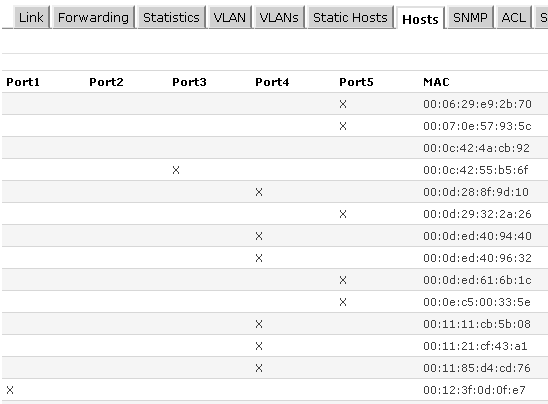
Hosts Screen:

Your standard mac address table
ACL Screen:
This is a filter table. You can get pretty crazy with this thing. You set specific ports that macs/ip addresses are allowed to be sourced from or travel to. If you want to drop a source mac, specify the mac address, then hit the redirect check box, but don’t specify an interface. Another interesting thing to note is the fact that there is the option to on the fly set or reset the VLAN ID of a frame to whatever you want…pretty wacky. If you could also specify a port you could do some DHCP filtering…which would be NICE. Some DHCP rogue mitigation would be nice.
This would make for a decent little switch with gig speeds. It has some interesting features, though I would like to see some spanning tree and syslog exporting. I also like how it shows up in Mikrotik neighbors.
What features would you guys like to see/what would you guys like to use this for?

(http://gregsowell.com/?p=2063).

Ubiquiti AIRMAX 5G20 Sector Antenna

Posted by Admin 0 comments
World Class Antenna Designs
Patent-pending next-generation technology achieves gain, cross-pol isolation, and beamshaping characteristics rivaling the highest quality cellular carrier basestation antennas in the world. Instantly pair with Rocket M5 to create a powerful AirMax 2x2 MIMO PtMP BaseStation. Rocket mount and weatherproof RF jumpers included.


5.15-5.85GHZ HI-GAIN BASE STATION ANTENNA, DUAL-POL 90-DEGREE 20DBI
Ubiquiti AIRMAX 5G20 AM-5G20 AIRMAX-5G-20-90 AM-5G20-90 5G-20-90 BaseStation Sector Antenna

Product Includes:
Sector Antenna
Antenna Bracket with the Rocket Fast Mount (for the Airmax BaseStation Model only)
Pole Brackets, bolts, washers and nuts
RF Jumper Cables (weatherproof)

Rocket M5 and AirMax BaseStation/Rocket Antennas have been designed to seamlessly work together. Installing Rocket M5 on AirMax BaseStation Antennas requires no special tools, you simply snap it into place with the mount provided with the Antennas.

Product Specifications:
• Frequency Range: 5.15-5.85 GHz
• Gain: 19.4-20.3dBi
• Polarization: Dual Linear
• Cross-pol Isolation: 28dB min
• Max VSWR: 1.5:1
• Hpol Beamwidth (6dB): 91 deg.
• Vpol Beamwidth (6dB): 85 deg.
• Elevation Beamwidth: 4 deg.
• Electrical Downtilt: 2 deg.
• ETSI Specification: EN 302 326 DN2
• Dimensions: 27.6x5.7x3.1in (700x145x79mm) diameter
• Weight: 13.0lbs (5.9kg)
• Windloading: 160 mph

(http://www.balticnetworks.com/ubiquiti-airmax-5g20-sector-antenna.html).

MikroTik R52nM 802.11a/b/g/n 300mW miniPCI Card

Posted by Admin 0 comments
R52nM dual band miniPCI card (300mW 2.4Ghz & 5Ghz)  Support in 802.11a/b/g/n with MMCX connectors gift you excellent perfomance for your wireless backbone.
Dual band IEEE 802.11a/b/g/n standard
• Output Power of up to 23dBm
• Support for up to 2x2 MIMO with spatial multiplexing
• Four times the throughput of 802.11a/g
• Atheros AR9220, chipset
• High Performance (up to 300Mbps physical data rates and 200Mbps of actual user throughput) with Low Power Consumption
• Two MMCX antenna connectors
• Modulations:
OFDM: BPSK, QPSK, 16 QAM, 64QAM
DSSS: DBPSK, DQPSK, CCK
• Operating temperatures: -50ºC to 60ºC
• Power consumption MAX 1.95W
• ESD protection +/- 12kV

http://www.balticnetworks.com/mikrotik-r52nm-802-11a-b-g-n-300mw-minipci-card-with-(mmcx-.connectors.html).

RouterBOARD 711-2Hn

Posted by Admin Wednesday, October 19, 2011 0 comments
Mikrotik Router RouterBOARD 711-2Hn - The RB711 is a small CPE type RouterBOARD wireless router with an integrated 2GHz 802.11b/g/n wireless card. RB711 includes RouterOS operating system which can be a router, firewall, bandwidth manager, a CPE and more - all at the same time.

This device has one MMCX connector allowing single chain connectivity. The integrated wireless card is capable of up to 27dBm transmit power output and has built-in 16kV ESD protection on RF and LAN ports.

Features mikrotik router RB 711-2n :
Performance: Atheros AR7241 400MHz CPU
Memory: 32 MB DDR SDRAM onboard memory
Ethernet: One 10/100 Mbit/s Fast Ethernet port with Auto-MDI/X
Wireless: Built in 2GHz AR9280 802.11b/g/n card, 1x1 MIMO, 1x MMCX connector
Operating System: RouterOS v4 Included and Level 3 License
Power Options: Passive PoE
Dimensions: 10.5 cm x 10.5 cm (4.13 in x 4.13 in) Weight: 67g
( For the specific feature set of a MikroTik license level, please see the MikroTik web site ).

Mikrotik SXT 5HnD Wireless N Support

Posted by Admin 0 comments
Mikrotik SXT 5HnD Wireless N SupportSXT 5HnD is a low cost, high speed 5GHz wireless device. Dual polarization 802.11n and Nv2 TDMA technology help to achieve even 200Mbit real throughput speed.

Mikrotik RB 1200 Review

Posted by Admin Tuesday, October 11, 2011 0 comments
Mikrotik router RB 1200 Review - The new and affordable rackmount router. It has ten individual gigabit Ethernet ports, five of them can be connected together in one 5-port switch group.

RB1200 has a SODIMM slot with bundled 512MB of RAM, a beeper and a serial port. It has no moving parts and it’s operation is completely silent, optional fan header is available. The RB1200 comes in a 1U aluminium rackmount case.

Specification Mikrotik router RB 1200 :

Product CodeRB1200
ArchitecturePPC
CPUPPC460GT 1000MHz
Current MonitorNo
Main Storage/NAND64MB
RAM512MB
SFP Ports0
LAN Ports10
GigabitYes
Switch Chip1
MiniPCI0
Integrated WirelessNo
MiniPCIe0
SIM Card SlotsNo
USBNo
Memory CardsNo
Power Jack110/220V
802.3af SupportNo
POE InputNo
POE OutputNo
Serial PortDB9/RS232
Voltage MonitorYes
Temperature SensorYes
Dimentions1U case: 44x176x442m
Operating SystemRouterOS
Temperature Range-20C .. +65C
RouterOS LicenseLevel6

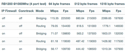
All throughput tests done with Xena Networks specialized test system and RouterOS v5, according RFC2544, with Ethernet frame sizes 64, 512, 1518 bytes. Each board is tested with specified number of Ethernet interfaces, to ensure optimal load on hardware.

Mikrotik RouterBoard High Speed Capacity

Posted by Admin 0 comments
Previous product line MikroBits has issued a series MikroBits Celoica 8101 Core 2 Quad, and now latest series MikroBits Celoica 8101 Quad Xeon (available ROS Level 4, 5 and 6), MikroBits Celoica rackmount solutions for the needs of large-capacity router, with an Intel ® Xeon ® Processor X3380 (12M Cache, 3.16 GHz, 1333 MHz FSB), 2 GB of RAM, and 10 gigabit ethernet ports. Fastest among other products.

Specification :

  • Processor : Intel® Xeon® Processor X3380 (12M Cache, 3.16 GHz, 1333 MHz FSB)
  • RAM : 2 x 667MHz DDR2 Slots, 2 x 1024MB Industrial Grade RAM (2GB RAM) installed on the base Model
  • Boot loader : Award 16 Mbit PnP Flash BIOS with function of BIOS redirected to COM port
  • HDD Interface : 2x SATA, IDE, 1x CF Slots with True IDE IBM MicroDrive Support
  • Compact Flash : 1 GB Industrial Grade Compact Flash for RouterOS
  • HDD : 250GB SATA 2.5" HDD
  • Ethernet : 10 x 10/100/1000Mbps Gigabit Ethernet (Intel® 82574L)
  • Lan by-pass : 2 groups, LAN1-LAN2, LAN3-LAN4Expansion Slots : 1 x 32bit/33MHz MiniPCI/1 x PCIe x8 slot
  • Serial port : 1 console, RJ type
  • LCDs : 1x back lit 2character x16 character LCD Display
  • LEDs : Power and HDD LED
  • Speaker : Mini PC - Speaker
  • Power : IEC C13 Power Cord, input power: 100VAC-250VAC 50Hz- 60Hz (International PSU)
  • Fan : 3x Redundant CPU/Power Supply /Chassis Fans,
  • Dimensions : 44 mm (1.73") (H) x 427.8 mm (16.93") (W) x 392 mm (15.43") (D)
  • Operating Temperature : 0°C ~ +45°C (32°F ~ 113°F)
  • Storage Temperature : -20°C ~ +70°C (-4°F ~ +158°F)
  • Humidity : 10% ~ 95% RH, non-condensing
  • Power Supply : 270W ATX PSU
  • Operating System : MikroTik Router OS v5
(rbmikrotik).

Mikrotik RouterBoard RB435g

Posted by Admin Saturday, October 8, 2011 0 comments
Five miniPCI slots and three Gigabit Ethernet ports give you enough connectivity options to use the RB435G as the central part of your network. Now with Gigabit ports, to properly utilize all the speed 802.11n with Nv2 wireless. Five miniPCI slots to be used for four sectors and a backbone, or any other configuration you need. The two USB 2.0 ports can be used for extending storage, adding a 3G wireless modem for backup connectivity,for a mobile installation or all together. The RB435G comes with a 680MHz Atheros CPU and is preinstalled with a Level5 RouterOS license.

CPU: Atheros AR7161 680MHz (800MHz option supported)
Memory: 256MB DDR SDRAM onboard memory
Boot loader: RouterBOOT
Data storage: 128MB onboard NAND memory chip and microSD slot for expansion
Ethernet: Three 10/100/1000 Gigabit Ethernet ports with Auto-MDI/X
miniPCI: Five miniPCI Type IIIA/IIIB slots
Expansion: Two USB 2.0 ports with powering (5V 1A supply)
Extras: Reset switch, beeper, temperature, voltage and current monitors
Serial port: One DB9 RS232C asynchronous serial port
LEDs: Power, NAND activity, 5 user LEDs
Power options: PoE: 8-28V DC on Ether1 (Non 802.3af). Jack: 8-30V DC
Dimensions: 105 mm x 154 mm, Weight: 153g
Power consumption: ~4.5W without extension cards
Output to cards: 19W without any cooling, up to 40W with active cooling
Operating System: MikroTik RouterOS, L5 license


(http://www.balticnetworks.com/mikrotik-routerboard-435g-rb-435g.html).

Netwatch DNS Failover

Posted by Admin 0 comments
The purpose of this script is to provide a solution for loss of service from ISP providers. The idea is for a topology where there are two different ISP providers, one of them provides a static IP and the other provides a dynamic IP address.

It is important to clarify that DNS should be usable from either ISP connection. This is because each ISP has its own DNS service. If a connection is lost it is likely that ISP 2 will not be able to connect to the DNS at ISP 1 and DNS requests will not be allowed to be resolved. The solution to this is to use a public DNS service such as OpenDNS.

/tool netwatch
add comment=Test1 disabled=no down-script="/tool netwatch set [find comment=\"Test2\"] disabl\
ed=no\r\
\n/tool netwatch set [find comment=\"Test1\"] disabled=yes" host=74.125.47.104 interval=\
30s timeout=2s up-script=""
add comment=Test2 disabled=yes down-script=":global GA\r\
\n:global GA [/ip dhcp-client get \"ether2 Fibertel\" gateway ]\r\
\n/ip route set [find comment=\"Fibertel\"] gateway=\$GA\r\
\n/ip route set [find comment=\"Telefonica\"] disabled=yes\r\
\n/ip route set [find comment=\"Fibertel\"] disabled=no\r\
\n/tool e-mail send to=\"EMAIL ADDRESS\" body=\"Connection with Telefonica Lost\
, Switched to Fibertel\" subject=\"Lost connection with Telefonica\"\r\
\n/tool netwatch set [find comment=\"Test3\"] disabled=no\r\
\n/tool netwatch set [find comment=\"Test2\"] disabled=yes" host=209.191.93.52 interval=\
30s timeout=2s up-script=":delay 10ms\r\
\n:log warning \"Started Test2\"\r\
\n/tool netwatch set [find comment=\"Test1\"] disabled=no\r\
\n/tool netwatch set [find comment=\"Test2\"] disabled=yes"
add comment=Test3 disabled=yes down-script="/tool netwatch set [find comment=\"Test4\"] disab\
led=no\r\
\n/tool netwatch set [find comment=\"Test3\"] disabled=yes" host=64.233.169.104 \
interval=30s timeout=2s up-script=""
add comment=Test4 disabled=yes down-script="/ip route set [find comment=\"Fibertel\"] disable\
d=yes\r\
\n/ip route set [find comment=\"Telefonica\"] disabled=no\r\
\n/tool e-mail send to=\"EMAIL ADDRESS\" body=\"Telefonica Connection Lost and Fi\
bertel took over, Trying to restore Telefonica\" subject=\"Loss of service type 2\"\r\
\n/tool netwatch set [find comment=\"Test1\"] disabled=no\r\
\n/tool netwatch set [find comment=\"Test4\"] disabled=yes" host=209.191.93.55 interval=\
30s timeout=2s up-script=":delay 10ms\r\
\n:log warning \"Started Test4\"\r\
\n/tool netwatch set [find comment=\"Test3\"] disabled=no\r\
\n/tool netwatch set [find comment=\"Test4\"] disabled=yes"

How it works:
The solution is composed of 4 netwatch tests.

The first (test 1) checks www.google.com, if for some reason this address stops responding to pings then it enables test2 and test1 disables itself.

Test2 pings www.yahoo.com, if the result is UP it enables test1 and test2 disables itself. If the result is "DOWN", test2 looks for the address of the gateway of the ISP on a dynamic IP and configures that address as a static route, followed by disabling the static route of the ISP on a static IP and enabling the dynamic IP route previously mentioned. It then sends an alert e-mail and enables test3 (for the new dynamic ISP) and test2 disables itself.

Test 3 and test4 do the same thing as test1 and test2 respectively. Only in this case, test4 would release the dynamic ISP and re-enable the static ISP.

(http://wiki.mikrotik.com/wiki/Failover_via_Netwatch_III_%28English%29).

Mikrotik Layer 7 Firewall Setup

Posted by Admin Monday, October 3, 2011 0 comments
Mikrotik Layer 7 Firewall Setup - Layer 7 is the application layer of the OSi system model and allows the Mikrotik router to analyze each and every packet that enters your network, and decide what to do with it.


The first step is to get a script file with the list of the most common Layer 7 protocols. This can be obtained from the Mikrotik Wiki via the following link :

http://www.mikrotik.com/download/l7-protos.rsc


We can now copy this script file into the Mikrotik 'Files' list.


Once you have the script file copied into the 'Files' window we can now proceed to import it via the terminal.
To make sure the script file imported properly, head to the 'IP' -> 'Firewall' menu and go to the 'Layer 7 Protocol' tab. You should now have a list ofthe most common types of traffic found within a network.


We can now create a firewall rule to block any type of Layer 7 traffic we choose. Go to the 'Filter' tab and add a new Firewall rule. Leave the chain set to 'forward'.


In the ' Advanced' tab you may now choose the Layer 7 traffic type you would like to block/allow.


Once the Layer 7 traffic type has been selected, proceed to the 'Action' tab and define the action of your choice. Drop is the most common action to stop a certain type off traffic flowing through your network.


Mikrotik RouterBoard RB493AH

Posted by Admin 0 comments
The RB493 has nine ethernet ports and three miniPCI slots, it also has a switch chip, so the ethernet ports 2-9 can be grouped together to make it act as a switch.

RB493 includes RouterOS - the operating system, which will turn this powerful system into a highly sophisticated router, firewall or bandwidth manager.

With nine Ethernet ports, and three miniPCI slots, this is our most versatile RouterBOARD model.

The RB493AH model includes the higher speed Atheros 680MHz CPU, more memory, and a Level5 license for more simultaneous tunnel interfaces and hotspot users.

Product specifications

Details
Product code RB493AH
CPU speed 680MHz
RAM 128MB
Architecture MIPS-BE
LAN ports 9
MiniPCI 3
Integrated Wireless 0
USB 0
Memory Cards 0
Power Jack 10-28V
802.3af support No
PoE 10-28V
Voltage Monitor No
Temperature range -30C to +60C
RouterOS License Level5

 (http://routerboard.com/RB493AH).

VLAN example on MikroTik Routers

Posted by Admin Thursday, August 11, 2011 0 comments
VLAN example on MikroTik Routers - Let us assume that we have two or more MikroTik RouterOS routers connected with hub. Interfaces to the physical network, where the VLAN is to be created is ether1 for all them (it is needed only for example simplification, it is NOT a must).

To connect computers through VLAN they must be connected physically and unique IP addresses should be assigned them so that they could ping each other. Then on each of them the VLAN interface should be created:


[admin@MikroTik] interface vlan> add name=test vlan-id=32 interface=ether1
[admin@MikroTik] interface vlan> print
Flags: X - disabled, R - running
#   NAME   MTU     ARP       VLAN-ID  INTERFACE
0 R test   1500    enabled   32       ether1
[admin@MikroTik] interface vlan>


If the interface were succesfully created, both of them will be running. If computer are connected incorectly (through network device thet does not retransmitt or forward VLAN packets), either both or one of the interface will not be running.

When the interface is running, IP addresses can be assigned to the VLAN interface.

On the Router 1:

[admin@MikroTik] ip address> add address=10.10.10.1/24 interface=test
[admin@MikroTik] ip address> print
Flags: X - disabled, I - invalid, D - dynamic
#    ADDRESS          NETWORK    BROADCAST     INTERFACE
0    10.0.0.204/24    10.0.0.0   10.0.0.255    ether1
1    10.20.0.1/24     10.20.0.0  10.20.0.255   pc1
2    10.10.10.1/24    10.10.10.0 10.10.10.255  test
[admin@MikroTik] ip address>


On Router 2:


[admin@MikroTik] ip address> add address=10.10.10.2/24 interface=test
[admin@MikroTik] ip address> print
Flags: X - disabled, I - invalid, D - dynamic
#    ADDRESS          NETWORK    BROADCAST     INTERFACE
0    10.0.0.201/24    10.0.0.0   10.0.0.255    ether1
1    10.10.10.2/24    10.10.10.0 10.10.10.255  test
[admin@MikroTik] ip address>


If it set up correctly, then it is possible to ping Router 2 from Router 1 and vice versa:

[admin@MikroTik] ip address> /ping 10.10.10.1
10.10.10.1 64 byte pong: ttl=255 time=3 ms
10.10.10.1 64 byte pong: ttl=255 time=4 ms
10.10.10.1 64 byte pong: ttl=255 time=10 ms
10.10.10.1 64 byte pong: ttl=255 time=5 ms
4 packets transmitted, 4 packets received, 0% packet loss
round-trip min/avg/max = 3/10.5/10 ms
[admin@MikroTik] ip address> /ping 10.10.10.2
10.10.10.2 64 byte pong: ttl=255 time=10 ms
10.10.10.2 64 byte pong: ttl=255 time=11 ms
10.10.10.2 64 byte pong: ttl=255 time=10 ms
10.10.10.2 64 byte pong: ttl=255 time=13 ms
4 packets transmitted, 4 packets received, 0% packet loss
round-trip min/avg/max = 10/11/13 ms
[admin@MikroTik] ip address>

Always Running Ethernet Interface On Mikrotik

Posted by Admin Thursday, July 21, 2011 0 comments

Some of X86 server based mikrotiks were showing “R” at ethernet interfaces although the cable is unplug. I did some quick searching and found that on X86 installs by default there is an option “disable-running-check” enabled. What this does is make the interface appear to always be running. As a byproduct if the interface always appears to be running, any IP addressing and routing is also still valid. This means that your router will still thinks this is a valid path.

With a quick command, you can revert this behavior to normal opperation:
In the below command I specified all three of my interfaces at once.


/interface ethernet set 0,1,2 disable-running-check=no
 
(MU).

Mikrotik Hotspot User Manager Backup

Posted by Admin Monday, July 18, 2011 3 comments
Mikrotik Hotspot User Manager Backup - Just simple script to backup and restore for all hotspot user account in user manager.

To backup, open the terminal then type :


/tool user-manager database save
 
And to restore :

/tool user-manager database load
 
Done.


Mikrotik Wireless Retransmits Check

Posted by Admin 0 comments

Wireless retransmission is when the card sends out a frame and you don't receive back the acknowledgment (ACK), you send out the frame once more till you get back the acknowledgment. Wireless retransmits can increase the latency and also lower the throughput of the wireless link.

To check if the wireless connection has wireless retransmissions you need to compare two fields in the wireless registration table: frames and hw-frames. If the hw-frames value is bigger than frames value then it means that the wireless link is making retransmissions. If the difference is not so big, it can be ignored, but if the hw-frames count it two, three or four times or even bigger than the frames count then you need to troubleshoot this wireless connection.

(wm).

Block Bit Torrent In Mikrotik

Posted by Admin Sunday, July 17, 2011 0 comments
The bane of most ISPs is Peer to Peer traffic(p2p). If you run hotels or apartments, especially apartments full of students, p2p will be your main source of issues. In some cases, extreme measure must be taken. So how does one go about taking back their network? The first thing to do is to find the offending traffic.
Mikrotik has some built in matching functionality for p2p traffic. You can use this in mangle rules or firewall rules. In mangle, you can mark the packets and then lower their precedence, or stick them in a smaller queue. In the firewall, you can block them all together.
Notice the many matches

New Model Of Mikrotik Wireless Router

Posted by Admin 0 comments

The omnitik is now going to be released. It is a cute little mimo omni outdoor radio, but also has a 5 ethernet ports. The only downside(and only an opininon) is that it is an A/N radio. I would like to see a B/G version. I would love to see the B/G version for golf courses and the like.

7.5 dBi antenna
400 Mhz proc
32 MB RAM
MSRP $119

Webfig Skins

They talk about webfig skins. This gives you the ability to customize the webfig interface. The only downside is that you don’t have the option to make the base page load straight to webfig when you browse to the router. It still loads to the generic Mikrotik screen which gives you the menu options for webfix/winbox/etc.

Wireless Options Simplified

They’ve merged ht-extension-channels into the channel-width option.

SXT Reflector

They highlight a 3rd party reflector that you mount the SXT on that narrows the beam with down by 20 dBi…25 down to 5. They are saying it buys you an extra 7KM.
Nothing really blowing my skirt up, but at least more product is hitting the market.


(gsw).

Wireless Point To Point Setup

Posted by Admin 0 comments
Mikrotik Wireless Point To Point Setup - When you are looking at a point to point (P2P) wireless link you will hear people mention “line of sight”. As in, if I stand at one point can I see where the other antenna will be mounted. I once thought “as long as I can see the other antenna, I’m good…right?” Not exactly. There is this tiny thing called the Fresnel zone.
Wikipedia will give you the complete scoop, so I will paraphrase :) The Fzone is the shape of the wireless signal between two radios.

What most people don’t realize is that the wireless Fzone between two radios is shaped like a football. It is actually fatter in the middle and tapers down towards the ends. What this means is that if you have a large obstruction in the middle of your Fzone, you will get degraded signal. Degraded signal means lower throughput and possibly no connection at all! So, how does one figure all this mess out?
Find point A’s elevation, point B’s elevation and the elevation of point M, which is the halfway point between A and B. A great place to find this info is here. This is Daft Logics altitude finder. It will give you the altitude for a point on a google map.
Lets say that site A is 100′, B is 200′ and M is 120′.


Our setup
What we want to do is take the site with the lowest elevation and make it 0 by subtracting itself:
Site A now: 100 – 100 = 0
Then subtract Site A’s original value from the other sites:
Site B now: 200 – 100 = 100
Site M now: 120 – 100 = 20
Site A = 0, site B = 100 and site M = 20.


Leveling the playing field.
Then find the distance between point A and B “as the crow flies”, aka a straight line. You can again use Daft Logic for this.
We will say that our distance is 10 miles.
Now visit an Fzone calculator like this one. Put in your distance and frequency and it will give you the height of the Fzone at midpoint. I’m saying my distance is 10 miles and my frequency is 5800. This gives me an Fzone height of 46′ at 5 miles (the halfway point).
So using all of this information I know that my Fzone midpoint will be 50′ at 5 miles(site A elevation + site B elevation / 2). This is the center of the Fzone at 5 miles, and we know that from our Fzone calc that the Fzone is 46′. If we divide that in half, we get 23′. So now we take our 50′ midpoint for the Fzone, subtract 23′ and last subtract the mid point M’s elevation which is 20 and we end up with 7′.


That's a spicy meatball.
It looks like the earth isn’t hitting our Fzone, but if anything stands higher than 7′ at that mid point, it will start to eat into our Fzone. What can we do? We can raise up our antennas to increase our distance from earth.

(gsw) .

Configure Mikrotik CPE Router

Posted by Admin Thursday, July 14, 2011 0 comments

This is my first post about the Mikrotik Product.  I will be putting up several examples in the coming weeks and months, so if you don’t see what you are looking for, be sure to contact me directly.  Leaving a comment is fine, but not likely to be “answered” unless it is a clarification for the specific article.
This article is intended to be a short guide to help you configure a Mikrotik router to behave in a way that is similar to a soho router with a wireless connection upstream.  This configuration is perfect for a WISP that is using devices like the RouterBoard 411 (priced at about $59), along with a CM9 or similar radio (about $40), associated power supply, outdoor enclosure/antenna, etc.  The total cost of a flexible device like this is about $150-160, including everything needed to install at a customer’s house or business.

This particular configuration features a DHCP server for the LAN clients, wireless upstream and a NAT function that will allow you, the WISP, to only require a single IP for the customer.  For the impatient, you can scroll to the bottom for a CUT/PASTE complete script without further ado.  For those that WANT further ado, read on…
Step one with a newly opened RouterBoard product is to log into the board.  Other articles explain that process, so I won’t take time to do it here.
Now, on with the explanation:
# Get rid of any static routes
/ip route remove [find]


This removes any routes that may have been added by the vendor you purchased your router from.  There are a few that may set this up.
#turn on all interfaces and delay for 3 seconds
/interface enable [find]
:delay 3

This bit of code will enable all interfaces on the router (including the wlan card, which is not “on” by default).  The “:delay 3″ line causes a pause in the processing of the script.  This allows time for the system to load the drivers for the wlan card.
# Set SSID and band
/ interface wireless
set wlan1 mode=station ssid="SET_ME" band=2.4ghz-b/g disabled=no

This is where you will configure the parameters for the operation of the wlan card.  In this example, we set the card to operate as a 2.4GHz client in either “b” or “g” mode.  Your network may be different, so set this accordingly.  You can determine the supported bands with the following command:
/interface wireless info print
The CM9 card, for example, supports the following bands:
2ghz-b, 5ghz, 2ghz-g, 5ghz-10mhz, 5ghz-5mhz, 2ghz-10mhz, 2ghz-5mhz
#Next, we set the identity:
#Set customer name here -- no spaces or crazy characters please
/system identity
set name="client_NAME"

This is the name that will show up in the top of Winbox and as part of the prompt in terminal mode.  You will, also, see this name in the “neighbor list” of other local routers (“/ip neighbor print”).  Setting this makes it pretty easy to see which device is which when connecting to multiple routers.
# Set the wireless card to get an IP via DHCP
/ ip dhcp-client
add interface=wlan1 add-default-route=yes use-peer-dns=yes \
use-peer-ntp=yes comment="This interface talks to the tower" disabled=no

If you provide your customers with an IP address via DHCP server at the AP, then this is the code you will use to set up the client side.  If you assign your customer a static IP address, then you can add that IP below and leave this portion of the configuration out.
# This should be the IP inside the network...
# Doesn't need to be changed unless the network demands it (private network)
/ ip address
add address=192.168.7.1/24 interface=ether1 \
comment="This is the customer's gateway" disabled=no

We are assigning the CUSTOMER LAN address here.  If they are using a different range of addresses (static assignments), then you may need to alter this address and the DHCP server below.  Also, you can add the “outside interface” (wlan card) IP address assignment here if that is the way your network functions.  You just have to duplicate the last 2 lines and set the “interface” to “wlan1″ and set the address appropriately.  Also, you will have to add the default route as follows:
/ip route add gateway=10.10.10.1
Just be sure that you set the gateway appropriately for your network.
# Configuration for the DHCP server for the LAN
/ ip pool
add name="dhcp_pool1" ranges=192.168.7.100-192.168.7.200
/ ip dhcp-server
add name="dhcp1" interface=ether1 lease-time=1d address-pool=dhcp_pool1 \
bootp-support=static authoritative=yes disabled=no
/ ip dhcp-server network
add address=192.168.7.0/24 gateway=192.168.7.1 dns-server=4.2.2.3


This code does several things, but as a whole, it sets up a DHCP server on the LAN side of the network.  If you changed the LAN IP above, you will need to make adjustments in this section of the configuration.  Note that the “dns-server” setting here is the server that is sent to the LAN clients.
# You can change the DNS to be what you want
/ ip dns
set primary-dns=4.2.2.2 secondary-dns=4.2.2.3 \
allow-remote-requests=yes cache-size=2048KiB cache-max-ttl=1w

Strictly speaking, the DNS servers here are not necessary, but are advised.  Just ensure that you use working DNS servers here.  One reason you may want to set these is if you want to create a caching dns server for the LAN clients.  If you want to do this, you can set the “dns-server” parameter above to point to the 192.168.7.1 (ether1 IP) address.  Note the option above that says “allow-remote-requests=yes“.  That is not a default setting (it’s off by default), so be sure that you turn it on if you want the caching dns server to work.
/ ip firewall nat
add chain=srcnat out-interface=wlan1 src-address=192.168.7.0/24 \
action=masquerade disabled=no

This section only has to be changed if you made changes to the LAN IP address above.  This is the code that sets up the router to masquerade (NAT) traffic out the wlan port.
That’s all there is to it! Below you will find the full script ready for you to hack to fit your network.  Just copy this code to the clipboard (highlight it, then hit CTRL-C), then paste it into notepad (or other favorite text editor), make appropriate changes and save it somewhere that is convenient for you.  To use it on a router, you simply connect to the NEW router, open a “New Terminal”, RIGHT-CLICK in the window and select paste.  That’s all there is to it!  Here’s the script in it’s entirety:
# Get rid of any static routes
/ip route remove [find]

#turn on all interfaces and delay for 3 seconds
/interface enable [find]
:delay 3

# Set SSID and band
/ interface wireless
set wlan1 mode=station ssid="SET_ME" band=2.4ghz-b/g disabled=no

#Set customer name here -- no spaces or crazy characters please
/system identity
set name="client_NAME"

# Set the wireless card to get an IP via DHCP
/ ip dhcp-client
add interface=wlan1 add-default-route=yes use-peer-dns=yes \
use-peer-ntp=yes comment="This interface talks to the tower" disabled=no

# This should be the IP inside the network...
# Doesn't need to be changed unless the network demands it (private network)
/ ip address
add address=192.168.7.1/24 interface=ether1 \
comment="This is the customer's gateway" disabled=no

# Configuration for the DHCP server for the LAN
/ ip pool
add name="dhcp_pool1" ranges=192.168.7.100-192.168.7.200
/ ip dhcp-server
add name="dhcp1" interface=ether1 lease-time=1d address-pool=dhcp_pool1 \
bootp-support=static authoritative=yes disabled=no
/ ip dhcp-server network
add address=192.168.7.0/24 gateway=192.168.7.1 dns-server=4.2.2.3

# You can change the DNS to be what you want
/ ip dns
set primary-dns=68.109.202.25 secondary-dns=10.21.11.1 \
allow-remote-requests=yes cache-size=2048KiB cache-max-ttl=1w

/ ip firewall nat
add chain=srcnat out-interface=wlan1 src-address=192.168.7.0/24 \
action=masquerade disabled=no


Source : http://blog.butchevans.com/2008/06/how-to-configure-a-mikrotik-router-to-replace-cpe-router/

Testing Mikrotik 802.11n Wireless Mini PCI Card

Posted by Admin Tuesday, June 21, 2011 0 comments
We tested a pair of RB600A devices, each populated with the new R52n card, that were each connected to a pair of antennas. Running a bandwidth test from a RouterBOARD 1000 on each end, we achieved up to 30000pps and 194.3Mbps throughput. The applications are limitless. With new laptops supporting 802.11n by default, you can increase your local network capacity four times of the previously possible speeds.


RB600A with R52n
Result units                                       Mbps       Pps

Routing w/ Conntrack                        183     15000

Routing wo/ Conntrack                      195     16000

Simple Prevent Bruteforce In Mikrotik

Posted by Admin 1 comments
/ip firewall filter add chain=input protocol=tcp dst-port=21
src-address-list=ftp_blacklist action=drop comment="Drop FTP brute forcers"
disabled=no

/ip firewall filter add chain=input protocol=tcp
connection-state=established action=accept comment="Allow packets belonging
to existing connections" disabled=no
/ip firewall filter add chain=input connection-state=related action=accept
comment="Allow packets related to existing connections" disabled=no


/ip firewall filter add chain=input protocol=tcp dst-port=22
connection-state=new src-address-list=safe action=accept comment="Allow SSH
safe hosts" disabled=no
/ip firewall filter add chain=input protocol=tcp dst-port=22
src-address-list=ssh_blacklist action=drop comment="Drop SSH brute forcers"
disabled=no
/ip firewall filter add chain=input protocol=tcp dst-port=22
connection-state=new src-address-list=ssh_stage3
action=add-src-to-address-list address-list=ssh_blacklist
address-list-timeout=10d comment="SSH brute forcers blacklisting"
disabled=no
/ip firewall filter add chain=input protocol=tcp dst-port=22
connection-state=new src-address-list=ssh_stage2
action=add-src-to-address-list address-list=ssh_stage3
address-list-timeout=1m comment="SSH brute forcers the third stage"
disabled=no
/ip firewall filter add chain=input protocol=tcp dst-port=22
connection-state=new src-address-list=ssh_stage1
action=add-src-to-address-list address-list=ssh_stage2
address-list-timeout=1m comment="SSH brute forcers the second stage"
disabled=no
/ip firewall filter add chain=input protocol=tcp dst-port=22
connection-state=new action=add-src-to-address-list address-list=ssh_stage1
address-list-timeout=1m comment="SSH brute forcers the first stage"
disabled=no

/ip firewall filter add chain=input protocol=tcp dst-port=8291
connection-state=new src-address-list=safe action=accept comment="Allow
WinBox safe hosts" disabled=no
/ip firewall filter add chain=input protocol=tcp dst-port=8291
src-address-list=wb_blacklist action=drop comment="Drop WinBox brute
forcers" disabled=no
/ip firewall filter add chain=input protocol=tcp dst-port=8291
connection-state=new src-address-list=wb_stage3
action=add-src-to-address-list address-list=wb_blacklist
address-list-timeout=10d comment="WinBox brute forcers blacklisting"
disabled=no
/ip firewall filter add chain=input protocol=tcp dst-port=8291
connection-state=new src-address-list=wb_stage2
action=add-src-to-address-list address-list=wb_stage3
address-list-timeout=1m comment="WinBox brute forcers the third stage"
disabled=no
/ip firewall filter add chain=input protocol=tcp dst-port=8291
connection-state=new src-address-list=wb_stage1
action=add-src-to-address-list address-list=wb_stage2
address-list-timeout=1m comment="WinBox brute forcers the second stage"
disabled=no
/ip firewall filter add chain=input protocol=tcp dst-port=8291
connection-state=new action=add-src-to-address-list address-list=wb_stage1
address-list-timeout=1m comment="WinBox brute forcers the first stage"
disabled=no

/ip firewall filter add chain=input protocol=tcp dst-port=22
connection-state=new action=accept comment="Allow SSH" disabled=no
/ip firewall filter add chain=input protocol=tcp dst-port=8291
connection-state=new action=accept comment="Allow WinBox" disabled=no
/ip firewall filter add chain=input protocol=tcp dst-port=20-21
connection-state=new action=accept comment="Allow FTP" disabled=no

/ip firewall filter add chain=input protocol=tcp dst-port=1337
action=add-src-to-address-list address-list=knock address-list-timeout=15s
comment="Port knocking the first stage" disabled=no
/ip firewall filter add chain=input protocol=tcp dst-port=7331
src-address-list=knock action= add-src-to-address-list address-list=safe
address-list-timeout=15m comment="Port knocking whitelisting" disabled=no

/ip firewall filter add chain=input action=drop comment="Drop everything
else"

/ip firewall filter add chain=output action=accept protocol=tcp content="530
Login incorrect" dst-limit=1/1m,9,dst-address/1m comment="Allow only 10 FTP
login incorrect answers per minute" disabled=no
/ip firewall filter add chain=output action=add-dst-to-address-list
protocol=tcp content="530 Login incorrect" address-list=ftp_blacklist
address-list-timeout=3h comment="FTP brute forcers blacklisting" disabled=no

Reset Mikrotik Password On RouterBoard

Posted by Admin Saturday, May 21, 2011 0 comments

To reset username and password mikrotik that installed on routerboard, wo only can do that with reinstalling mikrotik router os. You can use Net Install method to reset username and password on your mikrotik router board

Try this link to try reinstalling your routerboard.

Installing Mikrotik | Upgrade Router OS

Posted by Admin Sunday, May 8, 2011 0 comments

Using Winbox


  • Connect to your router with Winbox, Select the downloaded file with your mouse, and drag it to the Files menu. If there are some files already present, make sure to put the package in the root menu, not inside the hotspot folder!:

Advanced Mikrotik Hotspot Setup

Posted by Admin Friday, May 6, 2011 0 comments
Advanced Mikrotik Hotspot Setup - You can also go a step further and play with some other available options, as this only skims the surface of the hotspot capabilities.


1. To disable communication between wireless clients (recommended), disable the default forward option on the wireless interface.

interface wireless set wlan1 default-forward=disabled
2. To set up a wallet garden (pages people can access without authenticating), use the following command:

ip hotspot walled-garden add dst-host=www.website.com
3. To limit client bandwidth type the following, replacing profilename with the current hotspot profile in use and speed with the rate limit in bits per second:

ip hotspot profile set profilename rate-limit=”speed“
4. You can customise the login and status pages by editing the files in the hotspot directory of the Mikrotik box. You can access these via FTP.


Tunning Wireless Interface To Increase Throughput

Posted by Admin 0 comments
Tunning Wireless Interface To Increase Throughput - To increase the troughput of the mikrotik wireless link, i have did this way.

Enter interface wireless to tune.

Data Rates Tab:

- Select configure. start with smalest values in Supported Rates A/G, in this case 6Mbps.


Analyze Traffic Flow With Mikrotik Router

Posted by Admin Saturday, April 23, 2011 0 comments


In addition to monitoring the network, the admin can also identify the various problems that occur on a computer network. With the traffic flow will be able to analyze and optimize network performance.


This is the configuration :

[Admin @ MikroTik]> ip traffic-flow

[Admin @ MikroTik] ip traffic-flow> set enabled = yes interfaces = all

[Admin @ MikroTik] ip traffic-flow> target

[Admin @ MikroTik] ip traffic-flow target> add address = :2055 version = 9

(gb)

Equal Cost Multipath Routing With Mikrotik Router OS

Posted by Admin Tuesday, March 22, 2011 0 comments
This script demonstrates one method of doing automatic failover using the Netwatch function and using scripting to enable or disable gateways. This is probably not the most efficient way, but it works. I would welcome any input on how it can be improved.
The situation:

You have 2 lines going out to the internet - 10.0.0.12 and 10.0.0.13. You have setup a mangle to mark HTTP traffic (optional) and want to route http along the 2 lines using load balancing.
You setup the mangle:
/ip firewall mangle add
chain=prerouting protocol=tcp dst-port=80 action=mark-routing \
new-routing-mark=ecmp-http-route passthrough=yes comment=" Route HTTP \
traffic to ECMP" disabled=no

You set up ECMP (Equal Cost Multipath Routing) by using something like
/ip route add dst-address=0.0.0.0/0 gateway=10.0.0.12,10.0.0.13 \
routing-mark=ecmp-http-route comment="ECMP route for HTTP"
Now you have ECMP for HTTP only. This is nice because MSN messenger, banking websites and other programs and problem sites will not be broken in the same way it might be if you used ECMP for all protocols.
What I then do is for example mark SMTP traffic and route this out through 10.0.0.12:
/ip firewall mangle add
chain=prerouting protocol=tcp dst-port=25 action=mark-routing \
new-routing-mark=smtp-out passthrough=yes comment="SMTP Traffic" disabled=no
/ip route add
dst-address=0.0.0.0/0 gateway=10.0.0.12 routing-mark=smtp-out \
comment="SMTP Traffic out"
and route all other traffic through 10.0.0.13
/ip route add
dst-address=0.0.0.0/0 gateway=10.0.0.13 comment="Default Route to Internet"
Then I need to setup 2 routes to specific addresses to force the router through specific gateways to "test" the links. These should not be popular addresses with your users! Otherwise when a gateway goes down they will have no access to those sites. The addresses I am using as an example are 1.1.1.12 to test 10.0.0.12, and 1.1.1.13 to test 10.0.0.13.
Next I use the Netwatch Function to switch all traffic to the working gateway should any of the gateways fail:
/ tool netwatch
add host=1.1.1.13 timeout=2s interval=30s up-script="/ip route set \
\[find comment=\"Default Route To Internet\"\] gateway=10.0.0.13" \
down-script="/ip route set \[find comment=\"Default Route To Internet\"\] \
gateway=10.0.0.12 comment="" disabled=no
add host=1.1.1.12 timeout=2s interval=30s up-script="/ip route set \
\[find comment=\"SMTP Traffic out\"\] gateway=1.0.0.12" down-script="/ip \
\n" \route set \[find comment=\"SMTP Traffic out\"\] gateway=10.0.0.13
comment="" disabled=no
The problem is that the ECMP http route will still be active, therefore http traffic wont work, so I have 2 scripts to check if both gateways are up or down and take action accordingly:
/ system script
add name="ecmp-startup" source=":if ([/ping 1.1.1.12 count=1]=1 && \
[/ping 1.1.1.13 count=1]=1 && [/ip route get [find \
comment=\"ECMP Route For HTTP\"] disabled]=true) do={ :log info \"Both gateways up\" \
\n/ip route set [find routing-mark=ecmp-http-route] \
disabled=no}" policy=ftp,reboot,read,write,policy,test,winbox,password
add name="ecmp-shutdown" source=":if ([/ping 1.1.1.12 count=1]=1 && \
[/ping 1.1.1.13 count=1]=0) do={ :log info \"Gateway down\"\
\n/ip route set [find routing-mark=ecmp-http-route] \
disabled=yes}" policy=ftp,reboot,read,write,policy,test,winbox,password
Hi I found this error while trying to use this script, what worked for me was
ecmp start/shut script. Looks like  in the start and shut script (") are missing
from the find, well other the script works wonders for me. Thanks a lot savagedavid
ecmp starthp script
:if ([/ping 1.1.1.13 count=1]=1 && [/ping 1.1.1.12 count=1]=1 && [/ip route get \
[find routing-mark="ecmp-http-route"] disabled]=true) do={:log info "Both Gateways are up" \
/n/ip route set [find routing-mark="ecmp-http-route"] disable=no}
ecmp shutdown script
:if ([/ping 1.1.1.13 count=1]=0 || [/ping 1.1.1.12 count=1]=0) do={:log info \
"Gateway down" /ip route set [find routing-mark="ecmp-http-route"] disabled=yes}

Notice that it first checks to see if the route is enable before trying to re-enable it. Otherwise it will reset the route and users will be dropped momentarily.

Then finally schedule the scripts to check every 30 seconds:
/ system scheduler
add name="gateway-check" on-event="/system script run ecmp-shutdown
script run ecmp-startup" start-date=jan/01/1970 start-time=00:00:00 \
interval=30s comment="" disabled=no
(wimi)

AAA with Mikrotik + Microsoft IAS(Internet Authentication Service) & Active Directory

Posted by Admin 0 comments


Topolog

Step by step :

1) Set Radius Client to Active Directory Server, in this case IAS is for Radius Server.


[admin@MikroTik] /radius> add service=login,hotspot address=[ip address AD server] secret=123456 authentication-port=1812 accounting-port=1813

2) Make 2 groups, admin and viewer

Admin :
[admin@MikroTik] /user group> add name=admin policy=ftp,password,read,sensitive,ssh,test,winbox ,local,policy,reboot,sniff,telnet,web,write

Viewer :
[admin@MikroTik] /user group> add name=viewer policy=read,telnet,winbox

3) Activate the radius function.

[admin@MikroTik] /user aaa> set use-radius=yes

4) Windows configuration : make active directory full with dns local, than add IAS within Control Panel => Add or Remove Programs => Add/Remove Windows Components => choose Networking Services => click Details => choose Internet Authentication Servive. (note: do the same for DNS)


5) After IAS installed, next configuration is IAS that used for Radius Server and linked to mikrotik. (note: register IAS to active directory first).

i) Setting Radius Clients :
a. Create new radius clients
b. Input values below, with IP address is ip router mikrotik that directly connected to IAS. (note: shared secret must equal to IAS and at mikrotik)


ii) Setting Connection Requst Policies
a. Create new connection request policy , than next and choose custom policy.

b. Di policy conditions, klik add pilih opsi Client-IP-Address. Input IP Address to router mikrotik. Connection request policies used to authentication proccess between mikrotik with Microsoft IAS.

c. Click edit, choose advanced and remove attribt in advanced tab.


iii) Setting Remote Access Logging
a. Go to remote access logging, than click Local File. Set value as below or with your own config.


iv) Set remote access policies. This Configuration is for user authentication proccess and user authorization.

a. First we make admin authentikasi and authorization for admin user. Create new remote access policy. Choose custom policy, than custom for name. Than Click add, atribut,Windows-Groups atribut, After that, choose group from domain group that we make at active directory. group scope must global


b.Step two is , set profile from access policy. choose Edit Profile,uncheck MS-CHAPv2, MS-CHAP, CHAP. Just check PAP, SPAP. In Encryption tab uncheck No encryption.


c.Step trhee is authorization proccess. Go to the advanced tab, at list atribut choose Vendor-Specific. click add input value at Enter Vendor Code 14988 with status Yes. It conforms. click configure attribute, input vendor-assigned number : 3, at Attribute value input admin (note: attribute value same with group name in mikrotik yang telah dibahas pada tahap awal).


d.We got AAA Mikrotik with Active Directory + Microsoft IAS config.


(sky16 / fm)

Stats

About

Mikrotikz is Router OS that based in Linux kernel